Internet Protocol: A Deep Dive into Networking Essentials for backend engineer
The Internet Protocol (IP) serves as the backbone of modern communication, enabling the seamless flow of data across networks worldwide. Whether you’re sending a request to a server or receiving data from a backend system, the journey always involves IP packets. This blog unpacks the anatomy of IP and its associated concepts, offering a bridge between software development and network engineering.
The Role of IP in Networking
At its core, IP is responsible for encapsulating data into packets, providing each with a source and destination IP address. This abstraction occurs at Layer 3 of the OSI model. To routers and switches, an IP packet is merely a container of data; they aren’t concerned with application-specific details like HTTP headers or encryption.
Key Features of IP Packets:
-
Layer 3 Protocol: Operates independently of higher-level details such as ports.
-
Encapsulation: Data from protocols like TCP, UDP, or even encrypted payloads fits into IP packets.
-
Routing: IP packets are directed across networks using routing tables and subnet masks.
IP packets don’t inherently care about the type of data they carry. Whether it’s an HTTP request, a UDP packet, or a gRPC payload, everything fits into an IP packet for routing purposes. Understanding this basic premise is crucial for demystifying the complexities of networking.
Anatomy of an IP Packet
An IP packet comprises two main sections: the header and the data. While application developers often focus on the data payload, the header contains crucial metadata:
- Version: Indicates whether the packet uses IPv4 or IPv6.
- Header Length: Specifies the length of the header (typically 20 bytes, up to 60 bytes with options).
- Total Length: Includes both header and data, capped at 65,535 bytes.
- Source & Destination IPs: Essential for directing the packet.
- Time to Live (TTL): Prevents packets from looping indefinitely by decrementing at each hop.
- Fragmentation Fields: Allow packets too large for the Maximum Transmission Unit (MTU) to be split and reassembled.
Headers can also contain optional fields, extending their size from the default 20 bytes up to 60 bytes. However, additional header fields can sometimes lead to compatibility issues, as certain routers may block packets with options enabled.
The data section of an IP packet can hold up to 65,535 bytes. However, due to MTU limitations, packets larger than 1,500 bytes (the typical MTU) often require fragmentation, complicating transmission. In practice, large packets are rare, as developers aim to avoid the inefficiencies of fragmentation.
IP Addressing and Subnetting
IPv4 and IPv6:
IPv4 addresses are 32-bit numbers split into four bytes (e.g., 192.168.1.1). In contrast, IPv6 uses 128 bits, accommodating the exponential growth of devices connected to the internet.
Subnets:
An IP address is divided into network and host portions. The subnet mask defines how many bits belong to the network. For example:
- 192.168.1.0/24 indicates 24 bits for the network and 8 bits for hosts.
- Up to 254 hosts are possible in this subnet.
Subnets are critical for organizing networks and managing IP address allocations. Each subnet has a subnet mask, such as 255.255.255.0, which helps devices determine whether an IP address belongs to the same subnet.
Default Gateway:
When devices need to communicate outside their subnet, they send packets to a gateway, typically a router with interfaces in multiple networks. Routers use this information to direct traffic efficiently.
Routing and Communication
Routing is the process of forwarding packets between networks. Routers rely on subnet masks to determine whether a destination IP is local or requires forwarding.
Host-to-Host Communication:
- Within the Same Subnet: Devices communicate directly using MAC addresses.
- Across Subnets: Packets are sent to the gateway, which routes them to the appropriate destination.
Example: A host with IP 192.168.1.123 and subnet mask 255.255.255.0 wants to communicate with 192.168.2.200. The gateway directs the packet to the appropriate network since the two addresses are in different subnets.
Subnet Masking in Action: Subnet masks help identify whether an IP address is local or remote. For instance, applying a subnet mask (255.255.255.0) to 192.168.1.123 results in 192.168.1.0, identifying it as part of the 192.168.1.0/24 subnet. Communication between subnets requires routing through a gateway.
The Importance of Time to Live (TTL)
The TTL field is vital for preventing endless loops. Each router that processes a packet decrements its TTL by one. If the TTL reaches zero, the packet is dropped, and an ICMP (Internet Control Message Protocol) message is sent back to the sender. This mechanism is central to utilities like traceroute, which maps the path of packets across networks.
In networking, a hop refers to the journey of a data packet as it moves from one network device to the next, such as from one router to another. Each time the packet passes through a router, it is considered a hop. Key Points about Hops:
- TTL Decrement:
- The Time to Live (TTL) value in the packet's header starts at a set number (e.g., 64 or 128).
- Each router that processes the packet decrements the TTL by 1.
- If TTL reaches 0, the router discards the packet and sends an ICMP message back to the sender indicating a timeout.
- Why Measure Hops?:
- Hops are used to map the path a packet takes across the internet (e.g., with traceroute).
- They provide insights into the number of devices or networks between the source and destination.
- Routing Decisions:
- Each hop involves the router checking its routing table to determine the best path to the packet's destination. For example, if a packet travels from your computer to a website, it may pass through multiple routers, each decrementing the TTL and deciding where the packet goes next. These router-to-router transitions are the hops.
ICMP: A Diagnostic Tool
ICMP operates at Layer 3, providing essential network diagnostics. It is used in tools like ping and traceroute to:
- Report unreachable hosts or networks.
- Notify about packet expiration (TTL exceeded).
- Indicate the need for fragmentation when packets exceed the Maximum Transmission Unit (MTU).
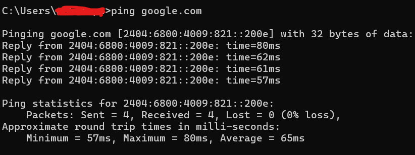
Example: Using Ping The ping command sends ICMP echo requests to a target device. If the device is reachable, it replies with an ICMP echo response, helping identify latency and packet loss. ICMP is fundamental for network diagnostics but is often blocked by firewalls to prevent misuse, such as flooding attacks.

Breakdown of the Output: Header:
Pinging google.com [2404:6800:4009:821::200e] with 32 bytes of data:- google.com: The domain being pinged.
- [2404:6800:4009:821::200e]: This is the IPv6 address of the Google server.
- 32 bytes of data: The size of each packet sent to the server.
Responses:
Reply from 2404:6800:4009:821::200e: time=80ms- Reply from 2404:6800:4009:821::200e: Indicates the server responded.
- time=80ms: The round-trip time for the packet, measured in milliseconds.
Other responses:
- The subsequent responses show round-trip times of 62ms, 61ms, and 57ms.
Ping stastics
Ping statistics for 2404:6800:4009:821::200e:
    Packets: Sent = 4, Received = 4, Lost = 0 (0% loss),
    Approximate round trip times in milli-seconds:
Minimum = 57ms, Maximum = 80ms, Average = 65ms- Packets Sent and Received:
- Sent = 4: Four packets were sent to the server.
- Received = 4: Four packets were received in reply.
- Lost = 0: No packets were lost during the communication.
- (0% loss): Indicates a stable connection.
- Round-Trip Times:
- Minimum = 57ms: The shortest time for a packet to travel.
- Maximum = 80ms: The longest time for a packet to travel.
- Average = 65ms: The average round-trip time across all packets.
Example: Using traceroute Traceroute is a command-line utility used to trace the path packets take to reach a specific IP address or domain. It provides valuable insights into the network infrastructure and can help diagnose connectivity issues or identify bottlenecks in the network.
How Does Traceroute Work? Traceroute works by sending packets with incrementally increasing Time-To-Live (TTL) values. Here’s how it operates:
- Packet Transmission:
- The first packet is sent with a TTL of 1. The first router in the path decrements the TTL to 0 and sends back an ICMP Time Exceeded message, revealing its identity.
- The second packet is sent with a TTL of 2. This process continues, revealing each subsequent router.
- Final Destination:
- When the packet finally reaches its destination, the server responds with an ICMP Echo Reply (or another relevant response), indicating that the trace is complete.
Protocols Used in Traceroute:
- Windows (tracert):Uses ICMP Echo Requests to perform the trace.
- Linux/Unix (traceroute): By default, sends UDP packets to high-numbered ports.Can be configured to use ICMP (-I option) or TCP (-T option).

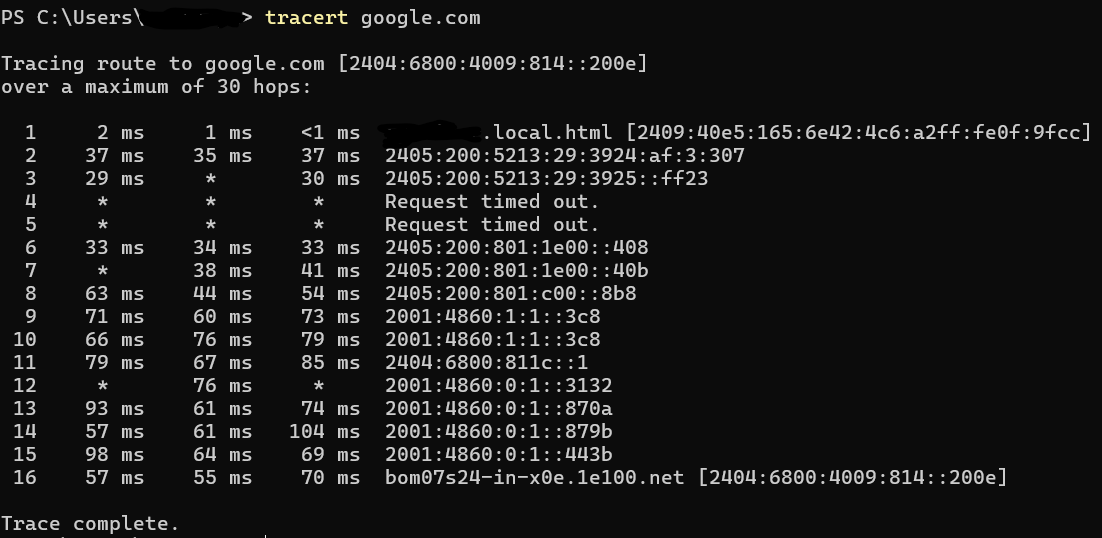
The image shows the result of a tracert (traceroute) command executed in a Windows PowerShell terminal. The command traces the route packets take to reach the target destination (in this case, google.com) by showing all the intermediate hops between the source and the destination. In networking, a hop refers to the journey of a data packet from one network device (such as a router or switch) to the next on its way to its destination. Each device the packet passes through is considered one "hop." The term is commonly used in tools like traceroute or tracert to measure and display the number of steps (hops) it takes for packets to travel from the source computer to the destination. Here the detials explaination :
- The command is tracing the route to google.com, which resolves to the IPv6 address [2404:6800:4009:814::200e].
- Maximum Hops: The traceroute is configured to stop after 30 hops if the destination is not reached earlier.
- Hops:
- Each line represents a hop, which is a router or network device the packets pass through to reach the destination.
- The latency for each hop is shown in milliseconds (e.g., 2 ms, 35 ms, 37 ms).
- Timeouts:
- Hops 4 and 5 show Request timed out. This typically happens when intermediate routers or firewalls block ICMP (Internet Control Message Protocol) packets, preventing the traceroute tool from getting a response.Timeout responses (hops 4 and 5) do not necessarily indicate an issue with connectivity; intermediate devices often do not respond to ICMP packets but still forward them successfully.
- Intermediate Addresses:
- Each hop lists an address (e.g., 2405:200:5213:29:3924:af:3:307) or a hostname (e.g., *.local.html) if DNS resolution is successful.
- These represent routers or devices that forwarded the packets.
- Latency Measurements:
- For each hop, the traceroute shows up to three latency values indicating the time taken for packets to reach and return from that hop.
- Example: In hop 2, the latencies are 37 ms, 35 ms, and 37 ms.
- Final Hop:
- Hop 16 is the destination, bom07s24-in-x0e.1e100.net, which corresponds to the server handling requests for google.com.
- The latency to the final destination is displayed as 57 ms, 55 ms, and 70 ms.
Practical Networking Insights for Developers
Understanding networking basics empowers developers to build efficient applications:
- Subnet Placement: Place databases and applications in the same subnet to reduce latency.
- Avoiding Router Congestion: Overloaded routers can delay or drop packets, impacting performance.
- Resource Optimization: Efficient use of headers and payloads minimizes unnecessary data transfer.
- Understanding Packet Anatomy: Familiarity with IP packet structure helps diagnose network delays and optimize communication.
For instance, placing a database and application server within the same subnet reduces the need for routers to process inter-subnet traffic, minimizing delays and potential congestion.
Conclusion
The Internet Protocol is a marvel of engineering, balancing simplicity and extensibility. By delving into its intricacies, software developers can optimize applications, collaborate effectively with network engineers, and better troubleshoot performance issues.
Whether you’re debugging a slow database connection or designing a scalable backend, understanding IP is an indispensable skill. With this foundation, you’re well-equipped to explore more advanced networking topics like congestion control, MTU optimization, and secure communication protocols.